· Esp32 · 4 min read
Controlling ESP32 GPIOs with micropython
The ESP32’s General Purpose Input/Output (GPIO) pins are essential for interfacing with sensors, actuators, and other peripherals in embedded projects. In this blog post, we explore how to control ESP32 GPIOs using MicroPython. You’ll learn how to configure pins as inputs or outputs, set or clear output pins, and read digital input states. With clear examples and step-by-step instructions, this guide makes it easy to harness the power of MicroPython for GPIO control, enabling you to build interactive and responsive projects with the ESP32, whether you’re a beginner or an experienced developer.
Introduction
In this article, you will learn how to control ESP32 GPIO using micropython. Specifically, you will learn writing programs to control digital input/output ports such as configure a pin as input or output, set or clear a pin, and read digital input from a pin. You will implement 2 simple projects:
- Blink an LED
- Detecting button press by reading digital input of a pin
Prerequisites
Hardware
You will need the following components:
| QTY | Component Name | Buy on amazon.com |
|---|---|---|
| 1 | ESP32 DevKit C | Amazon |
| 1 | LED Kit | Amazon |
| 1 | Resistor Kit | Amazon |
| 1 | Push button | Amazon |
| 1 | Breadboard | Amazon |
| 1 | Jumper Wire Kit | Amazon |
Affiliate Disclosure: When you click on links in this section and make a purchase, this may result in this site earning a commission at no extra cost to you.
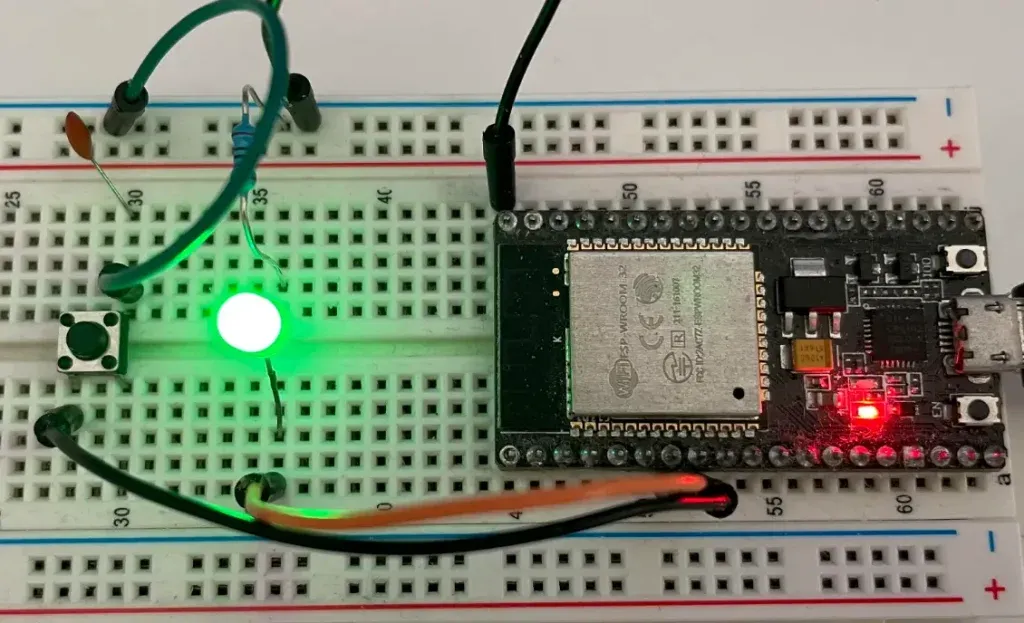
In our project in the next sections, you will connect a LED to GPIO pin 32 and a button to GPIO pin 33 of ESP32 DevKit C as following
Software
You should be familiar with the concepts of working with micropython with ESP32. If you are new to micropython programming, checkout our previous tutorial.
micropython Pin class
To control GPIO pins of ESP32 using micropython, you need to use objects from machine library. Therefore, the first thing you need to do is to import machine module
from machine import PinThe Pin class from machine module has methods that allow you to interact with underlying GPIO hardware. You will learn how to use this class in the next section.
Control digital output ports
To control a digital output port, for example, GPIO 32, you create an object of class Pin as following:
io32 = Pin(32, Pin.OUT)Now you can use variable io32 to set GPIO 32 high or low. To set the pin high, you use method value() and pass 1 as argument
io32.value(1) # set GPIO 32 highTo clear the pin, you call the method value() and pass 0 as the argument
io32.value(0) # clear GPIO 32Project Example
Now you will implement a simple micropython program to blink an LED connect to GPIO 32. To make the LED blink, you need to import another module time and use sleep() function to create delay. Your code may look like this:
from machine import Pin
import time

led = Pin(32, Pin.OUT)

while True:
    led.value(1)
    time.sleep(1)
    led.value(0)
    time.sleep(1)
Testing the code
To test this code, save the above code in a file named test.py. Make sure you flashed micropython binary on ESP32 first using esptool.py. Then use pyboard.py to load the above code to ESP32. Check instructions if you are unsure how to do it.
Control digital input ports
To control a digital input port, you need to create an object of class Pin as follow:
io33 = Pin(33, Pin.IN, Pin.PULL_UP)The above line will create an object named io33 associated with GPIO 33 and configure GPIO 33 as an input port with internal pull-up resistor. To read the value of an input port, you use the value() method. For example
print(io33.value())This method returns 0 if the pin logic is low, and returns 1 if the pin logic is high.
Project Example
Now let’s implement an example to demonstrate its usage. You are required to read the state of a button to see whether it is pressed or not. The button is connected to GPIO 33. If the button is not pressed, GPIO 33 is high, otherwise, it is low. When the button is pressed, you toggle the state of a LED and print out a message to console.
from machine import Pin
import time

led = Pin(32, Pin.OUT)
led_state = 0
led.value(led_state)

button = Pin(33, Pin.IN, Pin.PULL_UP)

while True:
    if button.value() == 0:
        print("Button pressed")
        if led_state == 0:
            led_state = 1
        else:
            led_state = 0
        led.value(led_state)

    time.sleep_ms(100)
In the above code, you have used a variable led_state to store the state of the LED. Whenever you detect the button is pressed, you toggle the state of LED accordingly.
Wrapping Up
In this article, you have learnt basic APIs to control GPIOs of ESP32 using micropython. To go further from here, you can check micropython machine Pin API reference and time module.