· Esp32 · 5 min read
Getting started with ESP32-DevKitC development board
The ESP32-DevKitC is an excellent starting point for exploring the capabilities of the ESP32 microcontroller. In this guide, we’ll introduce you to the key features of the ESP32-DevKitC development board, including its components, pinouts, and how to get your first program running. You’ll learn how to set up your development environment, connect the board to your computer, and create a simple “Hello World” program. With step-by-step instructions, this guide will help you hit the ground running and start experimenting with the powerful features of the ESP32-DevKitC.
Introduction
In this article, we take a look at an ESP32 development kit ESP32-DevKitC and understand its hardware, so that we can start writing firmware for ESP32 and building exciting WiFi-Bluetooth enabled projects.
Hardware Used
In this article, we will be using the hardware listed in the table below
| QTY | Component Name | Buy on amazon |
|---|---|---|
| 1 | ESP32 DevKit C | amazon.com |
Affiliate Disclosure: When you click on links in this section and make a purchase, this may result in this site earning a commission at no extra cost to you.
ESP32-DevKitC components
The below figure shows an ESP32-DevKitC development kit plugged in a breadboard and powered by USB.
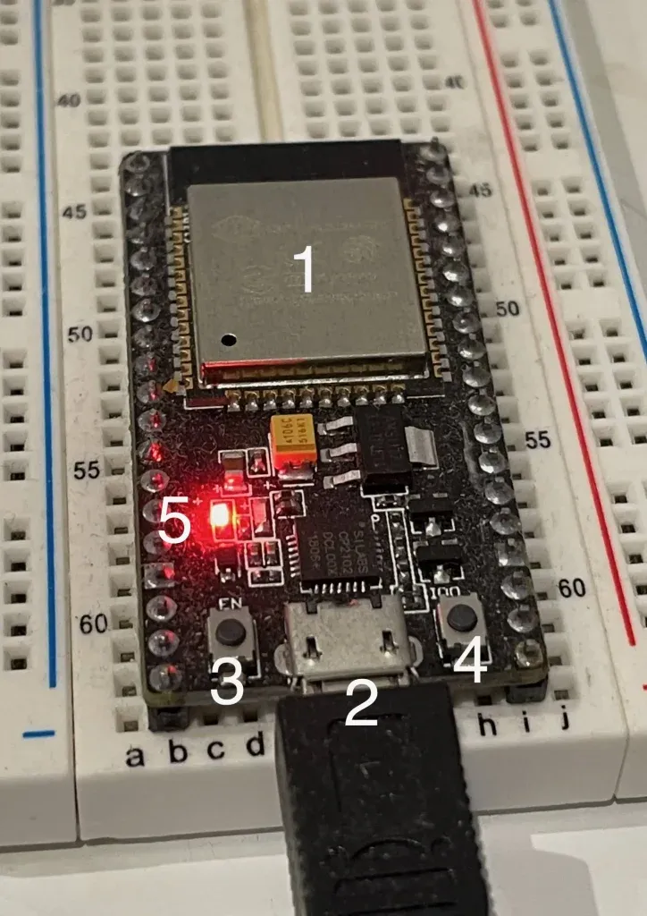
As shown in the figure, there are several notable components on the board:
- (1) ESP32-WROOM-32 module: This is the heart of the board, which encapsulates the following components:
- ESP32-D0WDQ6 processor which has two 32-bit Xtensa LX6 CPU cores that run on adjustable clock frequency from 80 MHz to 240 MHz. On-chip memory includes 448 kB of ROM, 520 kB of SRAM, 16 kB of SRAM in RTC, 1 kbit of eFuse.
- 40 MHz crystal oscillator
- 4 MB external SPI flash
- Antenna circuit for wireless communication (WiFi and Bluetooth)
- (2) Micro USB Port to provide 5V power and exchange data from a computer. The module integrates an USB-to-UART bridge chip CP2102N that allow data communication from ESP32 and a host computer via UART. Firmware can be uploaded to ESP32 via this serial interface. During development, logging messages can also be printed to a terminal console via this path.
- (3) EN Button. EN button is connected to EN pin of ESP32 (Pin 3). Normally, this pin is held high. When EN button is pressed, this pin is pulled low which causes a chip reset. Your program will run from beginning again after pressing EN button.
- (4) Boot button. This button is connected to IO0 pin of ESP32. During start up, if Boot button is held low, IO0 is kept low which makes the ESP32 to enter Download mode. In this mode, ESP32 waits to receive a new firmware over UART interface. Therefore, if you want to flash a new firmware to the ESP32, you need to hold Boot button, then press EN button to reset the chip. On booting up, it will check if Boot is pressed and enters Download mode to begin the firmware update process.
- (5) LED indicator. This LED is on when there’s 5V supply provided to the circuit.
Board pinouts
Next, let’s take a look at the I/O pins of the module. The below diagram illustrates the exposed pins and their functionalities.
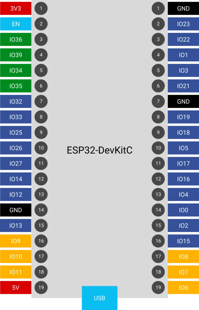
There are 19 pins on each side of the board, with some pins are connected to ground (marked as black color) or 3.3V or 5V (marked as red color). I/O pins are arranged on either sides. You need to refer to this diagram when building your circuits. Note that some of the pins have special functionalities that you need to be aware of.
| Pins | Notes |
|---|---|
| IO6, 7, 8, 9, 10, 11 (marked with yellow color) | These pins are connected to external SPI flash of the module. Avoid using these pins in your application as they may cause conflict with accessing flash memory |
| IO0 | This pin connects to the Boot button |
Test the board
To test if the board is working and getting basic information about the ESP32 chip, you will create a new project, build and flash a program to it, see log messages printed on terminal. Follow these steps
First, make sure you have completed the steps to install a development environment for ESP32 using ESP-IDF. If you are unsure where to get started, check out our previous article.
Next, create a new project based on the hello_world example project in ESP-IDF. The hello_world example contains simple code to retrieve chip information using ESP-IDF API.
Then build and upload the code. As explained earlier, you need to place ESP32 in Download mode before flashing a new program to it. For ESP32 DevKitC, you put ESP32 to Download mode by holding Boot button, then press EN button, then release both buttons. ESP32 will reset, and on booting up it will enter Download mode to receive the new firmware.
idf.py is a program that can transfer firmware to ESP32 over UART interface when ESP32 is in Download mode.
After new program has been loaded, the ESP32 resets and start executing your code. It will print out information about your board. If you get something like this printed on console, your board is working as expected
This is esp32 chip with 2 CPU core(s), WiFi/BT/BLE, silicon revision 1, 4MB external flash
The above output is printed out because of these lines of code
esp_chip_info_t chip_info;
esp_chip_info(&chip_info);
printf("This is %s chip with %d CPU core(s), WiFi%s%s, ",
            CONFIG_IDF_TARGET,
            chip_info.cores,
            (chip_info.features & CHIP_FEATURE_BT) ? "/BT" : "",
            (chip_info.features & CHIP_FEATURE_BLE) ? "/BLE" : "");
printf("silicon revision %d, ", chip_info.revision);
printf("%dMB %s flash\n", spi_flash_get_chip_size() / (1024 * 1024),
            (chip_info.features & CHIP_FEATURE_EMB_FLASH) ? "embedded" : "external");
Chip information is retrieved using ESP-IDF API esp_chip_info() and stored in a structure variable chip_info of type esp_chip_info_t.
Wrapping Up
In this article, you have learnt about the ESP32 DevKitC development board. You learnt about its components, pinouts and how to build and flash a simple program onto it. Now you are ready to explore WiFi/Bluetooth programming with ESP32.