· Nordic · 6 min read
nRF52 Serial Communication Using UART/UARTE
Serial communication is one of the most fundamental features in embedded systems, and the Nordic nRF52 makes it easy with its UART and UARTE peripherals. In this guide, you'll learn the differences between the two interfaces, and how to use the app_uart library from the nRF5 SDK to set up reliable serial communication. We’ll walk through initializing the UART, sending and receiving data, and handling common issues — all backed by a hands-on project example to get you started quickly.
Introduction
In this post, you will learn about serial communication using UART/UARTE modules in Nordic nRF52. We will discuss about:
- The difference between UART and UARTE modules
- How to use UART/UARTE modules in your projects
app_uartAPIs to control UART/UARTE in nRF5 SDK
To compile and run your code on real nRF52 hardware, it is recommended that you have a nRF52 development kit such as
Affiliate Disclosure: When you click on links in this section and make a purchase, this may result in this site earning a commission at no extra cost to you.
nRF52 UART/UARTE peripherals
In nRF52, there are two dedicated peripherals that facilitate serial communication using Universal Asynchronous Receiver Transmitter protocol: UART and UARTE modules. These modules allow the nRF52 chip to communicate with external devices by sending and receiving data using two wires (TX and RX). The difference between them is one module (UART) does not support EasyDMA, while the other one (UARTE) supports direct memory access mechanism using EasyDMA. The UARTE peripheral can use RAM regions as transmit and receive buffers. It is recommended to use UARTE if it is available.
Instances
Instances are copies of the same peripheral. One chip may contain one or more UART/UARTE instances. For example, nRF52832 contains one UART instance (UART0) and one UARTE instance (UARTE0). Both these instances share the same ID and base address (0x40002000), so they have the same allocated memory address, therefore, only one instance can be used at one time in your project.
nrfx_uart, nrfx_uarte and app_uart libraries
The UART and UARTE modules are controlled by nrfx_uart and nrfx_uarte drivers in nRF5 SDK, respectively. We will, however, not using these drivers directly. There’s library app_uart which simplifies our jobs when working with UART/UARTE. In the next section, I will show you how to use this library.
The app_uart library
In this section, we will walk through the steps needed to use UART/UARTE peripheral in your project. We will start with a blinky project template which does not have UART/UARTE support. You can download the project file here. This project template uses GCC and Makefile to manage the project. You might want to check our previous tutorial for steps how to create a new project.
Add UARTE source/header files
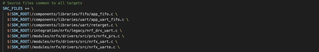
The first step is to include required source and header files in Makefile. There are a number of files that you need to include, as shown below. These are dependencies for app_uart module that we are going to use.
Enabling modules in project configuration
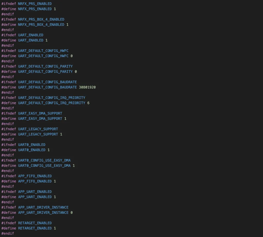
Open your project configuration sdk_config.h and insert the following definitions. There are quite a few definitions that you need to add:
- Enable peripheral resource sharing module. Since UART and UARTE share the same base ID and have the same address space in memory, UART and UARTE can not be used at the same time. This module reserves resources for a peripheral and avoid conflict when using peripherals with sharing resources.
- Enable the UART module and UARTE0 instance, set default parameters such as parity control, hardware flow control, baud rate, priority.
- Enable the APP_UART and APP_FIFO modules
Now you are ready to work with APIs in app_uart library. Let’s take a look at the APIs in app_uart library.
Initialisation
To intialise UART module, we use the macro APP_UART_FIFO_INIT:
APP_UART_FIFO_INIT(P_COMM_PARAMS, RX_BUF_SIZE, TX_BUF_SIZE, EVT_HANDLER, IRQ_PRIO, ERR_CODE)You need to specify a few parameters:
P_COMM_PARAMS: is a pointer that points to UART communication structure of typeapp_uart_comm_params_t. This structure contains information about which pins are used for UART communication, whether to use flow control and parity, and at what speed (in baud) it should use.RX_BUF_SIZEandTX_BUF_SIZE: specify the size of receiver and transmitter buffersEVT_HANDLER: a callback function to be invoked when an event happens in the UART module.IRQ_PRIO: specify tnterrupt priorityERR_CODE: the return code of the initialisation. If initialisation is successful, it will returnNRF_SUCCESS.
Internally, this macro calls app_uart_init() function to initialise the module.
Receiving a byte from UART
You use the function app_uart_get() to read a byte from the receiver buffer. If there is a byte in the buffer, it will be written to the address pointed by p_byte and the function returns NRF_SUCCESS. Otherwise, the function returns NRF_ERROR_NOT_FOUND.

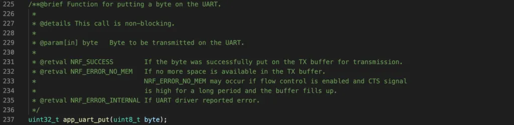
Sending a byte to UART
To send a byte to UART transmitting buffer, you call the function app_uart_put(). This function is non-blocking, meaning that the byte will be placed to the buffer and the function returns. The actual data might not be sent to the receiver immediately. If the function returns NRF_SUCCESS, it means there is still space in the transmitting buffer and the data is queued to send.
nRF52 UART sample project
To demonstrate the usage of app_uart library, we will implement a simple project: echoing a character. In this project, we will use the PCA10040 development kit that is connected to a host computer using USB cable. We will initialise the UART module to communicate with the host computer. When we type a letter on the computer’s keyboard on a UART console, it will send the character to the board. The board receives it, then send back the character to the computer to display on the terminal.
Computer -> character 'A' -> [UART nRF52] receives 'A', sends back 'A' -> ComputerCode
Add the following code to your main.c
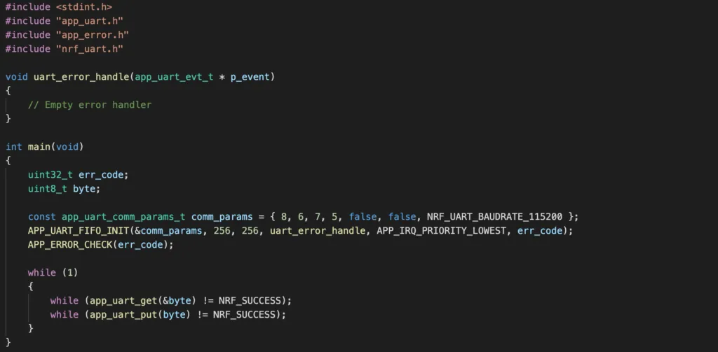
Full code project can be accessed on Github.
Flashing and testing the program
To flash the program, open a terminal and type make flash.
To test the program, connect the PCA10040 board to your computer, then open a terminal. We will be using screen as UART terminal. To access screen, use the following command:
screen [PORT] 115200where the [PORT] is your UART port, which can be determined by ls /dev/cu*. To exit screen, use key combination Ctrl + A then K. Now when you type a letter from your keyboard, you will see that it appears on the terminal. It has actually travelled from computer to UART module of nRF52, then travelled back from nRF52 UART to screen terminal.
Wrapping Up
In this guide, you have learnt about the UART/UARTE module in the nRF52 family and the app_uart in nRF5 SDK to control it. You also know how to add the required files and change project configurations in order to use UART module in your project. To go further from here, you can access Nordic Infocenter for full APIs. Thanks for reading.