· Stm32 · 5 min read
STM32 GPIO usage using HAL driver and STM32CubeIDE
STM32 microcontrollers offer versatile GPIO pins that can be used for a variety of tasks such as controlling LEDs, reading sensors, or interfacing with other devices. In this tutorial, we’ll walk you through how to control digital input and output ports of STM32 using the HAL GPIO library and STM32CubeIDE. You’ll learn how to configure GPIO pins for input or output, read input states, and toggle output states with simple code examples. By the end of this guide, you’ll be able to efficiently utilize STM32 GPIOs to interact with external hardware in your projects.
Introduction
In this article, you will learn basic functions to control digital input and output ports of STM32 using HAL GPIO driver. You will learn functions to:
- Configure a port as digital input or output port
- Enable/disable internal pull up/down resistor
- Set, clear or toggle an output port pin
- Read digital input from an input port
To compile and run your code on STM32 hardware, it is recommended that you have a STM32 development kit such as
- STM32 Nucleo-64 Development Board with STM32F303RE MCU
- STM32 Nucleo-64 Development Board with STM32F401RE MCU
- STMicroelectronics NUCLEO-F446RE STM32F446RET6 MCU
Affiliate Disclosure: When you click on links in this section and make a purchase, this may result in this site earning a commission at no extra cost to you.
STM32 GPIO HAL Control digital output
To set a pin as a digital output port, you can use the graphical tool in STM32CubeIDE. First, create a new project in STM32CubeIDE by selecting File > New > STM32 Project. Then enter STM32F103VB in the Filter, and select STM32F103VBx in the filtered list. Name the project gpio and click Finish.
Open gpio.ioc. In the Pinout & Configuration tab, set the clock frequency. Then click on the GPIO pin that you want to set as output port, for example, PD10, and choose GPIO_Output from the dropdown list. Click Save and Yes when it asks if you want to generate code automatically. Now STM32CubeIDE has generated some code to initialise pin PD10 as an output port in main.c.
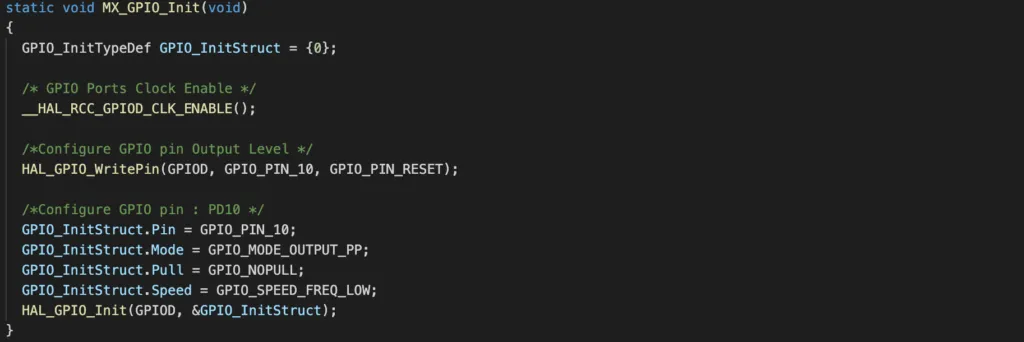
Let’s take a look at what functions are generated in main.c to initialise GPIO pin PD10.
By inferring the function name, you can see that
MX_GPIO_Init()is called to initialise GPIO/_ Initialize all configured peripherals _/ MX_GPIO_Init();
This function in turn calls HAL_GPIO_Init() API and take two arguments: the first argument is a pointer that points to the GPIO port address (in this case port D), the second argument is the address of a configuration structure which specifies parameters to configure GPIO_PIN_10 as output port.
You can right click on the function HAL_GPIO_Init() and select Go to declaration to see where this function is defined. It is defined in stm32f1xx_hal_gpio.c file located in the STM32F1xx_HAL_Driver as shown in the below diagram:
gpio
|---STM32F1xx_HAL_Driver
    |---src
        |---stm32f1xx_hal_gpio.c
Set or clear a STM32 GPIO output port
To set or clear a GPIO pin, you use the function HAL_GPIO_WritePin() which has the prototype
void HAL_GPIO_WritePin(GPIO_TypeDef *GPIOx, uint16_t GPIO_Pin, GPIO_PinState PinState);For example, if you want to set GPIO pin PD10, call
HAL_GPIO_WritePin(GPIOD, GPIO_PIN_10, GPIO_PIN_SET);If you want to clear GPIO pin PD10, call the same function, but replace the third argument with GPIO_PIN_RESET
HAL_GPIO_WritePin(GPIOD, GPIO_PIN_10, GPIO_PIN_RESET);STM32 GPIO HAL Control Digital Input Port
To configure a pin as digital input port, we will use the graphical interface again. Let’s say you want to configure PE13 as a input port with internal pull up resistor. You can open gpio.ioc and select Pinout & Configuration tab. Next, select pin PE13 and choose GPIO_Input from the dropdown list. Then click on System Core > GPIO > PE13 > PE13 Configuration. In GPIO Pull up/Pull down selection, select Pull up. Save and click Yes to generate code automatically.
If you open main.c and have a look at the function MX_GPIO_Init() again, you can see that a new block of code has been generated to configure pin PE13 as input port with pull up resistor.
/*Configure GPIO pin : PE13 */
GPIO_InitStruct.Pin = GPIO_PIN_13;
GPIO_InitStruct.Mode = GPIO_MODE_INPUT;
GPIO_InitStruct.Pull = GPIO_PULLUP;
HAL_GPIO_Init(GPIOE, &GPIO_InitStruct);
Read a STM32 GPIO input pin
To read the state of a digital input pin, use the function HAL_GPIO_ReadPin(). This function returns GPIO_PIN_RESET if pin value is low and returns GPIO_PIN_SET if pin value is high.
GPIO_PinState HAL_GPIO_ReadPin(GPIO_TypeDef *GPIOx, uint16_t GPIO_Pin);For instance, to read PE13 input pin, use
HAL_GPIO_ReadPin(GPIOE, GPIO_PIN_13);STM32 GPIO Project Example
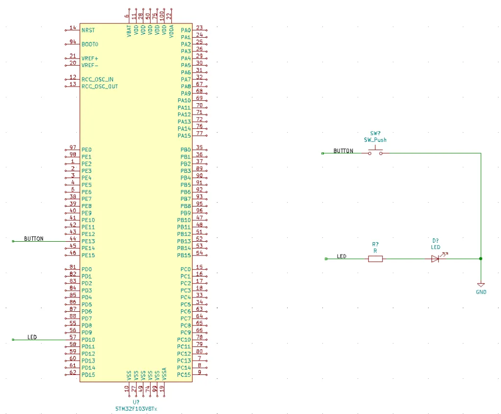
Now you have learnt the HAL functions to control digital input and output ports, it’s time to bring everything together and build a real project. In our project, we will implement a simple functionality: pressing a button will light up a LED, and if button is not pressed, the LED will turn off. The below diagram shows how the button and LED are connected to GPIO pins of STM32, button is connected to PE13 and LED is connected to PD10.
Follow the steps described above to configure PD10 as an output port and PE13 as an input port. Then add the following code to main.c in user code area
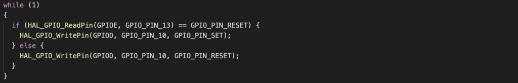
This code snippet checks repeatedly whether the button is pressed by reading the digital input level at GPIO E13. If button is pressed, the value it reads back is GPIO_PIN_RESET, then it will set the GPIO D10 in order to turn the LED on. Otherwise, it clears the GPIO D10 to turn the LED off.
Wrapping Up
In this article, you have learnt to use HAL GPIO driver to do basic tasks of controlling GPIO pins. In the next tutorials, we will learn more APIs and interact with other STM32 peripherals. Thanks for reading and see you in future posts.