· Stm32 · 5 min read
STM32 Serial Communication with UART
UART (Universal Asynchronous Receiver-Transmitter) is a fundamental feature of STM32 microcontrollers for reliable serial communication in embedded systems. In this blog post, we explore how to implement serial communication using STM32 UART with STM32CubeIDE. You’ll learn to configure the UART peripheral and use the HAL library to transfer data from an STM32 microcontroller to a host computer. With a step-by-step project guide, this tutorial is perfect for beginners and experienced developers looking to master UART communication for debugging, sensor interfacing, or data logging in STM32-based applications.
Introduction
Our objective in this project is to send data via UART from an STM32 chip to a host computer (which could be a Windows, Linux or Mac machine) and display the message on the host’s screen. In fact, the STM32 is not communicating directly with the host computer, but via an UART to USB bridge as shown in the diagram below
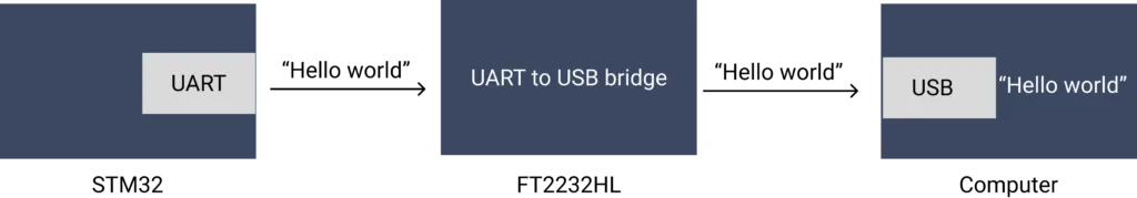 Project connection diagram
An UART terminal software is needed to display the message sent from the STM32. By going through this project, you will learn how to implement serial communication with STM32 UART.
Project components
Hardware
We will use the following components in our project
| Component | Description |
|---|---|
| DESTM32-S1 | STM32F103VBT6 development Kit |
| CJMCU-2232HL | USB to UART module, dual channels |
| JLink Lite Cortex M | STM32 Programmer |
STM32F103VBT6
In this project, we will use DESTM32-S1 development kit which has STM32F103VBT6 microcontroller with ARM Cortex M3 core, 80 IO pins, 128 kB flash and 20 kB of SRAM. If you are using a different development kit, you will need to check its datasheet and make necessary adjustment to each step below.
The STM32F103VBT6 chip has 3 USART modules (USART1, USART2 and USART3). If you take a look at the Device Configuration Tool in STM32CubeIDE, you will see that the RX and TX pins of these modules are hard-wired to specific IO pins as listed in the below table
| Pin | Description |
|---|---|
| PA9 | USART1_TX |
| PA10 | USART1_RX |
| PA2 | USART2_TX |
| PA3 | USART2_RX |
| PB10 | USART3_TX |
| PB11 | USART3_RX |
In our project, we will use USART3 module and pin PB10 and PB11.
CJMCU-2232HL
CJMCU-2232HL is a cheap dual channels UART to USB module which uses FT2232HL chip. It has USB interface and several exposed IO pins. The table below listed the relevant pins to our project
| FT2232HL pin | CJMCU-2232HL pin | Description |
|---|---|---|
| 16 | ADBUS0 | UART TX - Channel A |
| 17 | ADBUS1 | UART RX - Channel A |
| 38 | BDBUS0 | UART TX - Channel B |
| 39 | BDBUS1 | UART RX - Channel B |
You will need to install VCP driver (Virtual COM Port driver) on your host machine for the computer to talk with the FT2232HL chip.
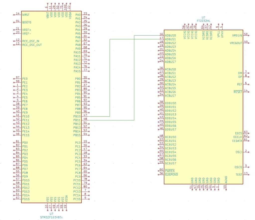
Wiring
For the STM32 to communicate with the CJMCU-2232HL module, you need to connect TX pin of USART3 to RX pin of channel A of CJMCU-2232HL, and connect RX pin of USART3 to TX pin of channel A of CJMCU-2232HL as shown below
| STM32 pin | CJMCU-2232HL pin |
|---|---|
| PB10 | ADBUS1 |
| PB11 | ADBUS0 |
If you use one of the following development kits, you don’t need the CJMCU-2232HL UART to USB module as USB interface is integrated to these kits already
- STM32 Nucleo-64 Development Board with STM32F303RE MCU
- STM32 Nucleo-64 Development Board with STM32F401RE MCU
- STMicroelectronics NUCLEO-F446RE STM32F446RET6 MCU
Affiliate Disclosure: When you click on links in this section and make a purchase, this may result in this site earning a commission at no extra cost to you.
Software
We will be using STM32CubeIDE as the development environment. If you are new to STM32 development, check out our previous article to get started with STM32CubeIDE.
Building STM32 UART project
Create a new project in STM32CubeIDE
Now open STM32CubeIDE and select File > New > STM32 Project. The STM32 Target Selection dialog will open which you can choose your target STM32 chip. Enter STM32F103VB in the Part Number filter (or choose your target STM32 chip). Then choose STM32F103VBTx variant and click Next button. Enter a name and select location for your project and hit Finish.
You will see the Device Configuration Tool window. In Pinout and Configuration tab, select USART3 peripheral, select Asynchronous as the Mode of communication, and disable hardware flow control. In the Parameter Settings section, choose the following parameters:
- Baudrate: 115200 baud
- Word Length: 8 bit
- Parity: None
- Stop bits: 1
We are going to use the same parameters on the host’s UART terminal, so that two devices can communicate with each other. In the Pinout window, you can see that pins PB10 and PB11 are highlighted in green as USART3_TX and USART3_RX. Click Save button and Yes when it asks whether you want to generate code.
If you inspect main.c file, you can see that the following function has been automatically generated for you
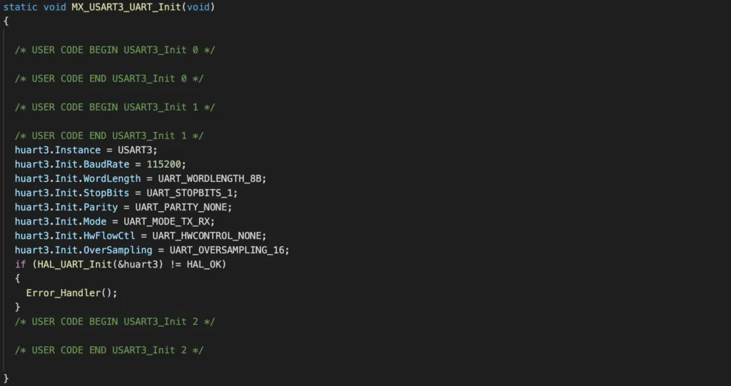
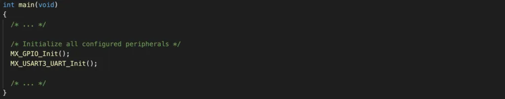
This function’s job is to configure the USART3 module using the HAL driver HAL_UART_Init() with the parameters we have specified in the previous step. It is invoked in main() during initialisation
To refer to USART3 in the code, you can use the global variable huart3 structure defined at the top of code.
/* Private variables ---------------------------------------------------------*/
UART_HandleTypeDef huart3;
Add code to send data over UART
Now you are ready to send data over UART. For example, if you want to send a string “Hello World”, you would need to call the function HAL_UART_Transmit() as shown below
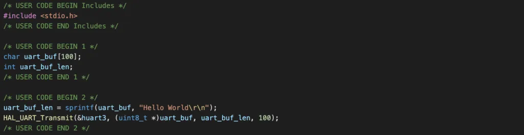
Here we use the function sprintf in stdio library to format the text and place it in to a buffer. Then we call HAL_UART_Transmit() and specify to use USART3 module with the address of transmit buffer and buffer length, and a timeout value.
Compile and flash the program
To compile the program, click Project > Build Project. To flash the program, you will need a programmer, which we use SEGGER JLink Lite Cortex M in our project. You will need to create a Run configuration and specify SEGGER JLink as the programmer. Then click Run.
To see the message sent over UART, you will need a UART terminal. On Linux and Mac, you can use the screen program. Open a terminal and enter
screen [PORT] 115200where PORT is the virtual COM Port which you can check by running ls /dev/cu* or ls /dev/tty*. Typically, it will list the ports like this
/dev/cu.usbserial-FD3100 /dev/cu.usbserial-FD3101Note that you will see 2 ports corresponding to two channels of FT2232HL chip (Channel A and Channel B). Since we wired UART pins to channel A, pick the one correspond to channel A. You will see the text Hello World printed on the terminal if everything is working properly.
Wrapping Up
In this article, you have learnt how to transfer data using STM32 UART. This is especially useful during development process where you want to see current code execution of your program. Thanks for reading.